Linear Timelapse Robot v1
Just in case anyone is following me via RSS, I just posted a new static page about my latest electronics project, a prototype motion control robot for making timelapse movies.
HD44780 LCD Interface lib for Teensy++ 2.0
Just a quick post to announce that I’ve posted a new project page to the static part of my site: Teensy++ Interface Library for HD44780-Based LCDs
It’s about a recently completed electronics hobby project.
My Latest Profile Picture: What’s Inside
I’ve recently updated my social media profiles with a new profile picture / avatar, receiving positive response and some curiosity. This is the image, at a high resolution:
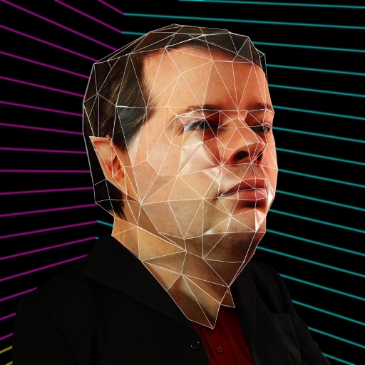
This is a picture of me wearing a picture of me. Read on to find out how this was done.
In 2010 the Electronic Arts Capture Lab had an open house, where employees from the rest of the studio could go by for demos of their equipment. See the video in the above link for examples of what we saw.
One thing they demonstrated was the facial capture rig they used to create high-resolution 3D models of actors’ faces. You can see the rig and part of the process between 0:09 and 0:17 in the video at the above link. It’s a rig containing a lot of digital cameras arranged spherically around the subject, and set up to fire in synchrony along with strategically placed flashes. Specialized software then takes all those photographs and correlates the features visible in them to deduce a textured, 3D digital model of the subject. This is one example of the science of photogrammetry. There is a longer discussion of this process in this thread post.
My colleague David Dixon and I had the idea to use these digitized models of our heads to construct actual physical models of our heads, at a larger-than-life scale, and wear them as Halloween costumes.
David, being the 3D editing wizard among the two of us, simplified the models from thousands of polygons down to dozens. Here are before (top) and after (bottom) screenshots of my model showing his work. Note the bottom one uses a corrected version of the skin texture (which I unfortunately lost the high-resolution version of) which explains the differences in skin tone and detail.
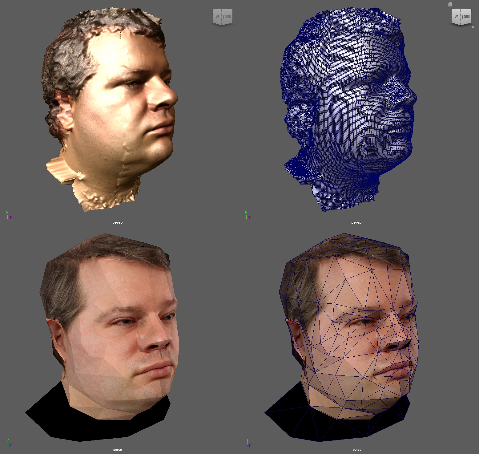
You can see the original model had quite a bit of surface noise to be cleaned up, including what looks like fractures in my cheeks but are probably registration errors.
We then imported the simplified model into Tamasoft PepaKura, which segmented it into flattenable pieces and added glue tabs, resulting in many pages of fragments that looked like this:
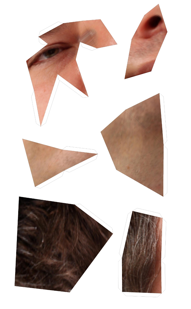
We had these printed on stiff paper at Staples, then spent hours gluing them together.
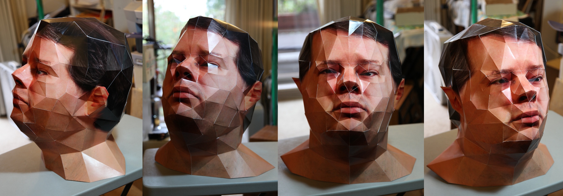
Here’s what mine looked like from a few angles the morning I finished it (I worked overnight to finish it in time):
And here are David and I showing them off at the office later that day:
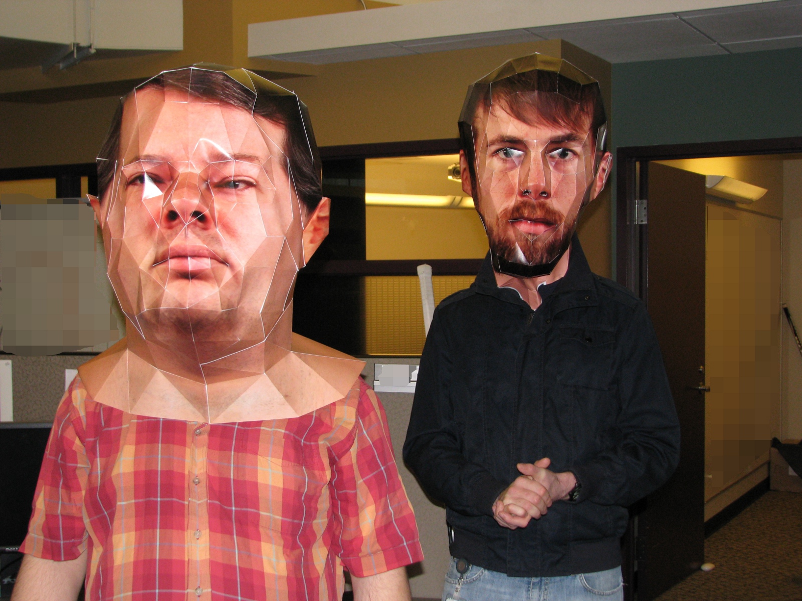
For the profile picture image, I set up a mini studio in my apartment and had my visiting parents help me fit my suit jacket over the shoulders of the model (since I can’t see anything when I’m wearing it) and operate the camera for me. I then digitally emphasized the edges between the polygons and removed the background and replaced it, appropriately, with one of the iconic Max Headroom backgrounds.
So there you have it: A long, technical and involved but creative and fun project that lets me wear an oversized 3D photo of my head over top of my real head.
Only took me 20 years…
The latest addition to my mad science lab: A device programmer.
There’s a lot of history behind this purchase.
Back when I was taking Electronics Engineering Technology in Toronto, twenty years ago, we had to do a sort of “mini-thesis” project in our final year. I really wanted to make an EPROM programmer for my project, because having one would enable me to incorporate stored-program components like microprocessors into my electronics hobby projects, and I couldn’t afford to buy one.
The instructor (hi, Darrell!) said this project wasn’t complex enough and would only be worth a ‘C’ grade at best, so I was forced to choose something else. But I’ve been wanting a device programmer ever since.
Lately I’ve been having a hankering to dust off the hobby and do some projects, and being able to use programmable devices is necessary for many of the projects I have in mind. I thought about making my own again, but I decided to check and see if prices on commercial models had got a little more reasonable. While I place value on doing stuff myself, making my own is now less interesting than the things I can do once I have one, so I’m willing to sacrifice some nerd cred in order to get to the good stuff faster.
Prices haven’t improved (most professional models are still in the thousands of dollars) but there are some cheap alternatives available now. I looked at what could be had from local dealers and from eBay, and I was tempted by these things called Willem programmers. They typically plug into a PC’s serial or parallel port, though some models now support USB, and they’re super cheap.
Unfortunately upon doing some research, I found that buying a Willem looked risky. Willems started out as a hobbyist design, which got picked up and mutated by others. There are now dozens of different models, many of which do not come with documentation or with functioning software – the Willem name has become so fragmented that there is even a visual identification guide to try to help people figure out which one they’ve got, so they can try to make it go. There are also some unscrupulous dealers doing things like naming their products “True Willem Programmer” to make it sound more credible than it is (“True” is part of the name, not a description).
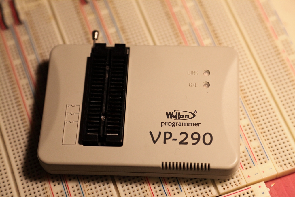
So I could go cheap and buy a Willem and risk having to spend a lot of time hunting down software, or maybe even reverse-engineering the thing to write my own, or I could drop a little more on a prosumer model. I settled on the Wellon VP-290 pictured above after reading some favorable reviews on hobbyist websites, and a brand new one set me back less than $200. It has an impressive list of supported devices, which more than covers my needs.
I haven’t actually burned any devices with it yet – I haven’t decided on my next project, let alone written the firmware. But I did test the programmer by reading out the contents of some old EPROMs I had sitting around, and while the software workflow isn’t slick, it’s good enough. I think this will prove to be a fruitful purchase.
So: I’m letting out a long sigh after twenty years of holding out. I had a lot of emotional investment in making my own device programmer – that initial rejection of the project idea got my hackles up and I never forgot it. But time heals all markets, and I’ve finally put it to rest and enabled myself to move on to bigger and better projects.
A thing I have finished
I’ve been craving a feeling of accomplishment for a long time, and I promise myself that over the Christmas holidays I would make an effort to finish at least one of my personal projects. And I did! And it feels good.
For a while I’ve been needing some bright lights for my macro photography, and also wanting some bright color accent lights. I bought this from ThinkGeek. It has the advantage of simply plugging into a standard light socket, and has sixteen different color settings. I found it still a bit too dim, and some of the colors were off – blue especially looked too purple for me.
So I decided to make my own – a larger one using multiple super-bright LEDs of four colors (red, green, blue and white) arranged in a mosaic with a diffusing filter in front to mix the colors. With this arrangement I should be able to get a much better variety of colors, and using multiple LEDs would give me more brightness.
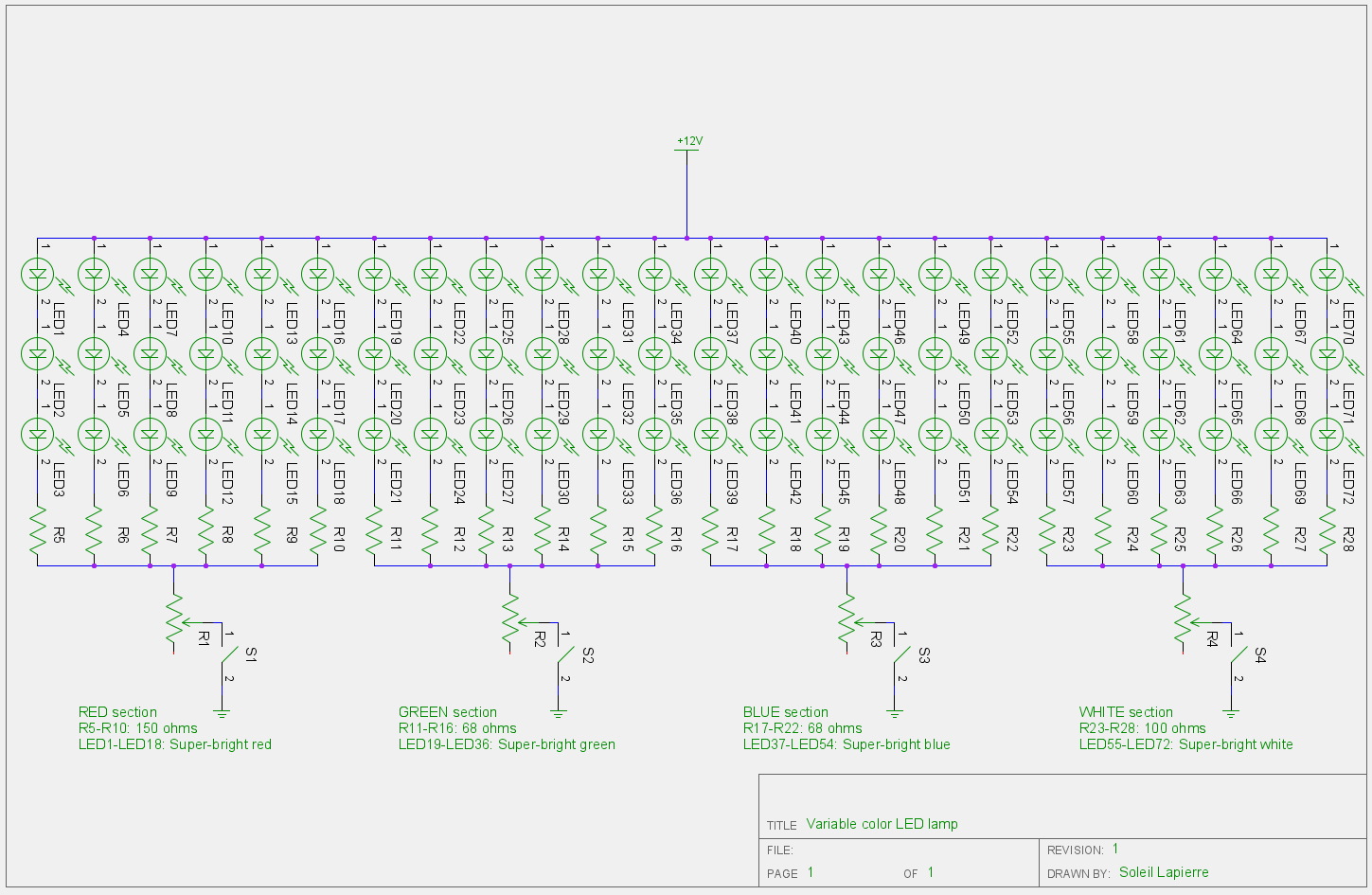
I based the physical design around available enclosures, protoboards and power supplies. I don’t like working with high voltages (they tend to be a bit killey) so I’ll always use an off-the-shelf power supply if I can. I decided on a 12V, 1A supply I had on hand because using a higher voltage would let me place the LEDs more in series, thus reducing the current requirements and the number of current limiting resistors I would need. Most super-bright LEDs have voltage drops between 3V and 4V, so that let me put them in series of three.
Here’s the schematic (click to embiggen):
I decided to socket the LEDs in female header strips instead of soldering them to the protoboard, in case I burnt some of them out and needed to replace them. In practice this perhaps wasn’t such a good idea; it complicated the physical layout of the circuit on the protoboard, and generated problems with loose connections between the LED leads and the sockets. I could probably solve the latter problem well enough by bending the ends of the leads slightly, but it seems to work well enough if I don’t shake it too much, and it’s easy to fix if a connection fails.
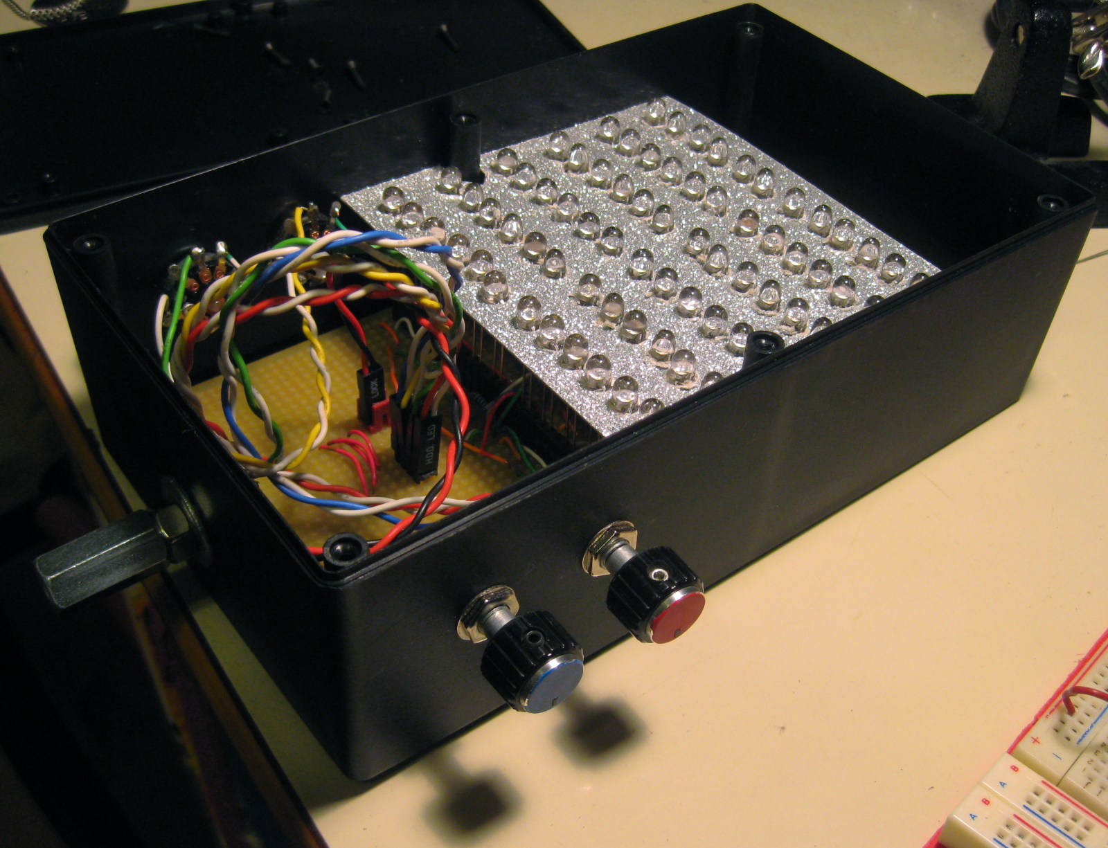
Here’s a picture of the finished board, populated with LEDs, installed in the enclosure I picked for it.
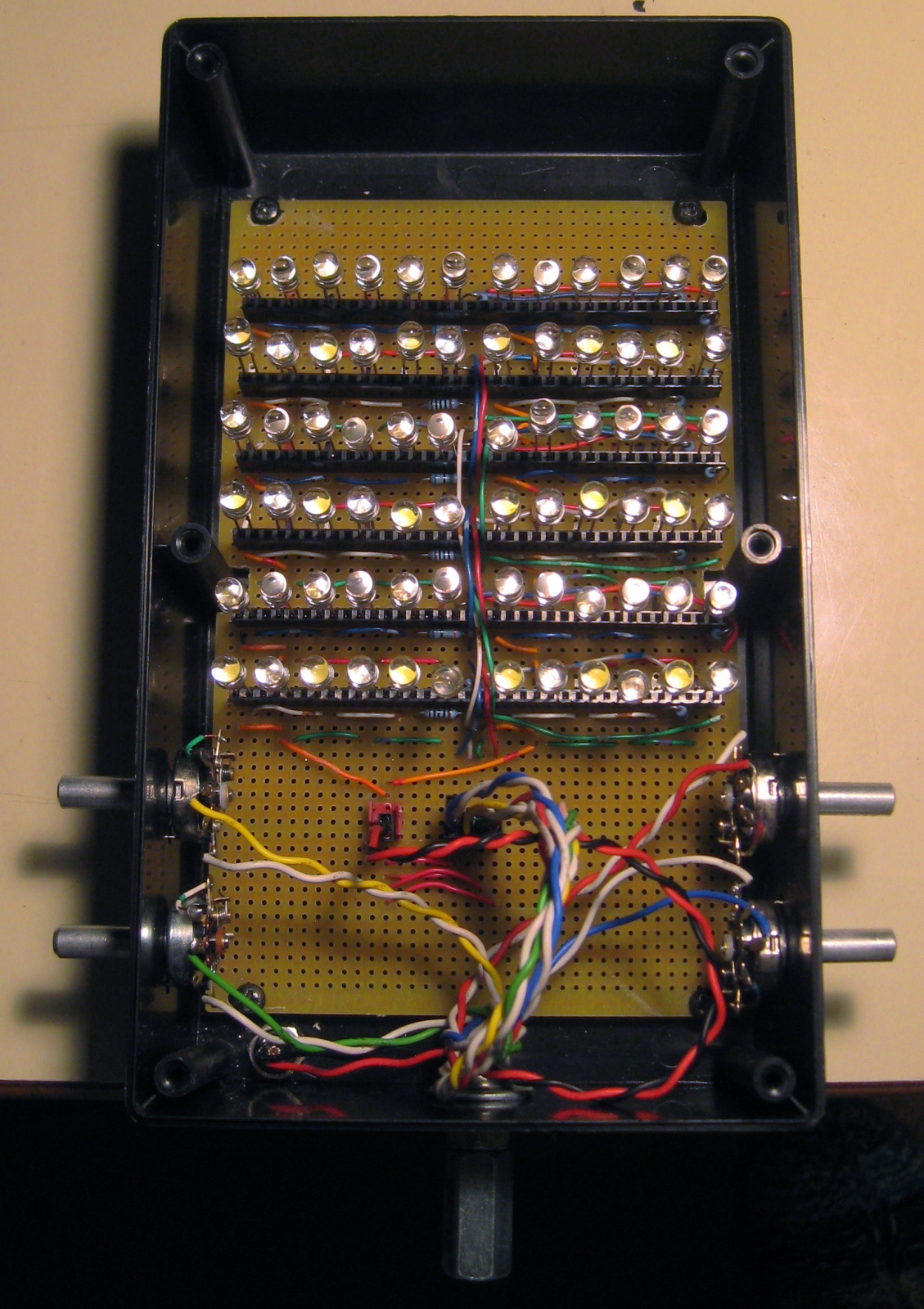
You can see the four brightness control potentiometers installed on the sides. At the bottom is a cheap tripod mount I made with a quarter-inch bolt and bolt joiner.
The next picture shows the reflective, scattering backdrop I put the LEDs through to help blend the colors. Since I was planning to put a diffuser in front of the LEDs, I figured there would be a lot of light back-scattered and so I should put a reflector at the back to stop some of the light from being wasted.
 I also added the color-coded knob handles to the controls in this shot.
And finally, here it is with the diffuser on the front:
 I made the diffuser myself by cutting a thin sheet of clear Perspex to size, then grinding both sides with coarse and then smooth sandpaper. It worked out well.
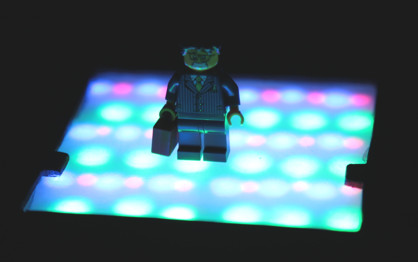
Although I had intended the light to be mounted vertically on top of a tripod or light stand, someone pointed out to me at this point that it could also be used horizontally as a small light table. It kind of looks like a disco floor when used this way:
And now, the results! To see if my project achieved its goals of brighter light and better color than the light I bought from ThinkGeek, I shot the following series of images (click to enlarge please). All images were shot using the same exposure and a fixed color temperature of 5400K. The upper row shows the primary colors of the ThinkGeek light, and the lower row is mine. Mine has an extra photo for white – the dim one is just the white LEDs, and the bright one is with all LEDs on at full intensity.
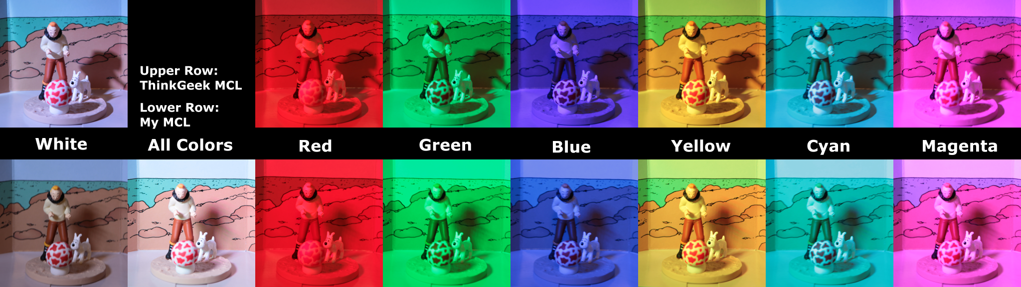
Conclusions:
- Mine is not as much brighter as I had hoped (perhaps half a stop for individual colors) but it is still brighter. The full-on white is considerably brighter.
- Mine has a slightly more bluish blue.
- The diffuser/reflector arrangement worked out well; when used as subject lighting rather than as a light table, the color mixture is very smooth. I could get more brightness by using a clear front panel instead of a diffuser, but then the colors would be less evenly mixed.
- Mine consumes slightly more power (9W versus their 7W) but that’s not a huge difference.
- Mine can produce a much wider variety of colors by virtue of having separate analog brightness controls for each of the four color components.
- Mine produces softer shadows on small objects because the light-emitting surface is relatively large; the ThinkGeek light is almost a point source so gives hard shadows.