As my cow-orkers know, I like kitschy mobile desk toys like lava lamps and Newton's cradles. Some gift shops used to sell these things that look like fortune-scammers' crystal balls but with a swirling iridescent liquid inside. One branded 'Mystic Lite' was a semi-favorite of mine for a while, but it eventually failed. A component (SCR or triac, I'm not sure) on the circuit board inside failed, rendering the swirling motor inoperable.
For a fun little project, I decided to try and repair it. I couldn't identify the part number of the failed component, so insead why not replace the whole board with one of my own design and improve the product in the process?
But first, there were some annoying air bubbles at the top of the globe - commonly seen with these cheap ones. Turns out the liquid was held in by a large rubber seal across the bottom of the globe. I turned it upside down and poked a syringe through to extract the air bubbles, then sealed the hole by poking a pinhead through to block it from inside and rubber-glueing the outside end. (Sorry, didn't think to take any process pictures of this part.)
I thought this would be a fun microcontroller project to add some more advanced behavior, but I'd need some extra components for that.
The motor itself was still good, and replacing it would have been beyond my skill because I couldn't see how the shaft passed through the seal without leaking, and didn't want to mess with that. I decided to make the new circuit randomly vary the motor speed and occasionally reverse it, to create more varied turbulence. DC motor speed is easily controlled via PWM (pulse-width modulation), which is where you control the ratio of on time to off time. A microontroller can do the timing part but cannot provide enough current to power even a small DC motor, so I needed to add a motor driver component. I added two in the common H-bridge configuration, which allows both control of high currents to drive motors, and reversal of their direction.
There was an air shaft extending into the center of the globe for the light inside. The shaft and the lamp support inside were just big enough for a large RGB led, so that's what I put in there. I also programmed the microcontroller to randomly vary the color output and brightness. For driving the LED a microcontroller output *might* be enough but I decided to use transistors for each of the three color channels, because then I could be sure to get maximum brightness without straining the microcontroller outputs, and could also calibrate the maximum current for each color, as different colored LEDs typically have different voltage drops.
Here's the schematic (click to embiggen). The KiCAD schematic is also available in my repo for this project.
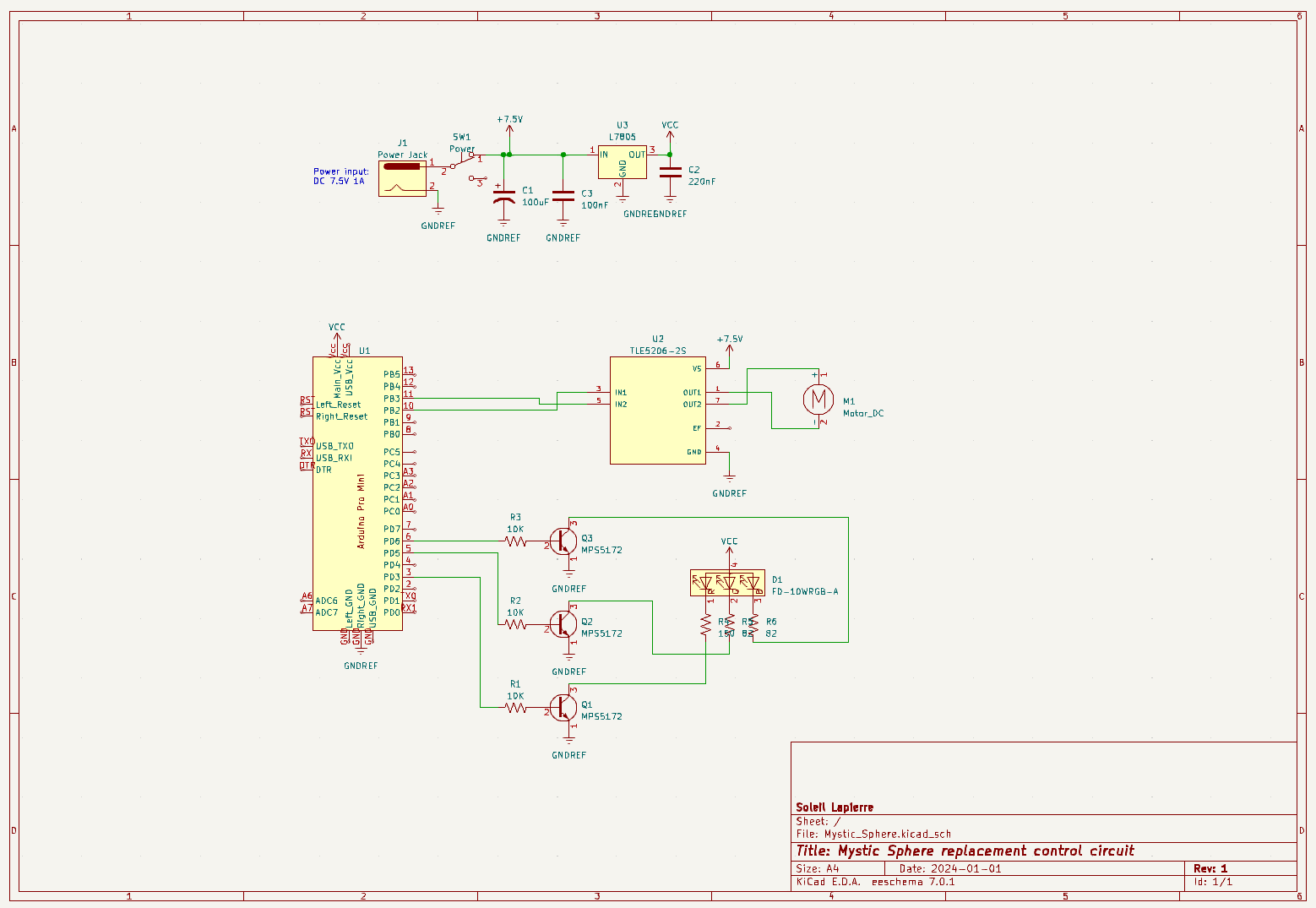
The circuit is really simple. It relies on an external wall-wart power supply providing 7.5 VDC for the motor, and internally regulates that down to 5V for the digital circuitry.
The microcontroller does all the work, outputting PWM signals to control the three colors of the LED and an H-bridge motor driver, which allows reversing the direction of the motor.
The more complex part of this project was the code running on the microcontroller, though honestly it's not really complicated at all. The code can be seen here.
The Arduino SDK provides an analogWrite function that takes care of producing a PWM signal to approximate a given analog value, so I just needed to generate values to represent the motor speed and direction and the intensities of the three LED colors.
The usual way Arduino programs work is that you provide an initialization function and an update function that gets called in a loop by the Arduino system software, between any other service routines it needs to do. I wanted the motor speed and the LED brightnesses to change gradually over time, so I wrote a utility class meant to be called iteratively in the main loop to increment or decrement a single value until it reaches a target value, then a new random target value will get set. I used this class multiple times for each of the quantities.
Some tweaking was required. I set up the LED driver circuitry so that I could output a maximum value to get approximately maximum brightness without burning out the LED, so that wasn't a problem. However, the motor would stall if I tried to make it go too fast, and it turned out that in the reverse direction it would start making an annoying knocking noise as much lower than the stall speed. I spent quite a few iterations finding values that would operate the motor reliably and quietly.
Here's a video showing ten minutes of the resulting behavior. You will see the light color and brightness change and the fluid swirling change direction and intensity several times.
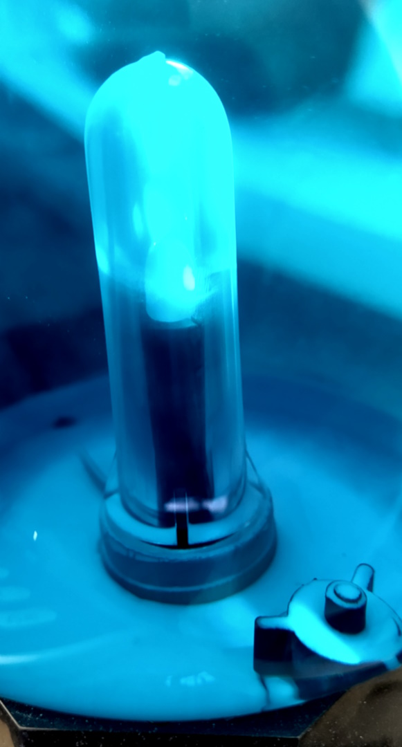
Here's a photo showing what the inside looks like after the mica power has been given a few weeks to settle out. You can see the stirring head of the motor at lower right, and on the left is the air column in the center of the liquid where the LED is mounted.
My main dissatisfaction with this project is that the cyan tint of the existing fluid limits the range of colors that can be seen. I'd like to be able to see some reds and yellows but that's not possible due to the filtering effect. If I were to do this over again I would replace the fluid with white or colorless fluid - either another mica powder suspension or oil with glitter in it.