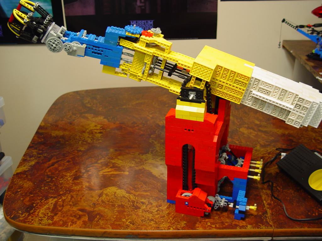

Overview of the arm from both sides.
After the surprising success of my previous robot arm I decided to rebuild it from scratch, this time with an improved gripper and powered by an electric motor. I wanted to get incrementally closer to making a Lego version of Radio Shack's Armatron toy.
I kept the basic structure of the arm the same but increased its size. I used universal joints for all places where the power train needed to flex (ie, at the joints) because I found the method of using a free-wheeling crown gear introduced lateral stress on joints, caused undesirable secondary motion when a joint moved, and wasn't very strong - the crown gears would often slip under high torque.
This time around I bought a couple of gear packs from Lego shop-at-home to get some gear types I didn't have before and to increase my supply. I totally redesigned the wrist and gripper to take advantage of the large turntable gear, and I'm really proud of how that part turned out. I also designed a manual transmission in the base of the arm so that all the movements could be powered by a single motor, as in the Armatron.
This arm has five degrees of freedom:
- The gripping claw opens and closes, and is strong enough to pick up a small Lego model.
- The claw rotates 360°.
- The wrist bends up and down and has a range of about 120°.
- The elbow bends horizontally and has about 120° of freedom. Although I constructed both the wrist and elbow joints to be able to flex through 180°, in practice they are limited by the use of universal joints to pass power through the joint.
- The shoulder rotates the arm up and down and has a range of about 90 degrees.
The transmission has an engage-disengage control for each axis of motion, and bidirectional motion is accomplished by reversing the electric motor. This limits the ability to move multiple axes at once. Overcoming this would have required a transmission twice as complex, and since this was my first time building a transmission I wanted to keep it as simple as possible.
One more degree of freedom is needed to equal the Armatron - a rotating base. I could have mounted the whole arm on a rotating base and also powered that with the motor, but then the controls would move with the arm, which is icky. Having stationary controls would require passing five power axes (or one plus four control channels) through a swivel joint, and I have not yet figured out a way to do that with Lego. In the Armatron it is accomplished with nested double-sided ring gears, but Lego does not have such gears. Another way - much simpler - would be to use a seperate motor for each joint. This seems to be the way most Lego robot arms are built. But I only have one motor and I wanted the challenge of running everything with it. The sacrifice was losing the moving base.
This arm uses about 85 gears, and I really had to gear down to get sufficient torque to move everything and pick up objects. As a result, the arm's motion is deathly slow. This is another problem that could be overcome by using multiple motors.
The Lego motor I used has a shaft speed of 350RPM, or 5.833 rotations per second. This table shows the gear ratio and effective movement rate for each part of the arm:
| Joint | Cumulative Gear Ratio (Joint axle to Motor) | Time for Full Arc | Comments |
|---|---|---|---|
| Grip open/close | 1:2592 | ~80 seconds | Conservative estimate of 60° difference between open and closed positions. Also there is some play in the mechanism. |
| Wrist rotate | 1:26244 | 75 minutes! | For a full 360° rotation. |
| Wrist up/down | 1:43740 | 40 minutes | For an estimated 120° of motion. |
| Elbow left/right | 1:14580 | 15 minutes | For an estimated 120° of motion. |
| Shoulder up/down | 1:37800 | 27 minutes | For an estimated 90° of motion. |
There are still plenty of things that can be improved in this design, but for now I think I'm done with building robot arms in Lego. At least until I get some more motors.
Here are some more pictures of the arm with discussion. At the bottom I have provided LDraw/MLcad files showing the construction of the gripper and the power train.


Gripper in open and closed positions.
The above images show the gripper in its fully open and fully closed positions. At its widest it can fit about ten studs between the two halves.
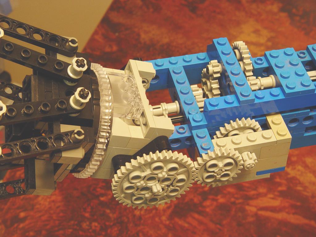

Wrist detail.
Here are closeups of the wrist joint from the left and right sides. The large grey gear on the left controls the wrist elevation and is driven from the axle on the underside of the blue section of the arm. The gears on the right side of the arm control the wrist rotation; they move a small gear inside the wrist turntable that causes the black half to rotate while the clear half remains stationary (not shown because it's mostly hidden by other bricks; see the MLcad file below if you want to see how it's built). In the second picture you can clearly see the black worm gear that opens and closes the grip.


Elbow detail.
The above pictures show detail of the left and right sides of the elbow joint. Most of the gears inside the frame of the upper arm (yellow) are for converting the horizontal plane of axles to a vertical plane so that they can pass through the elbow joint. The additional gears on the right (stud) side nearer the joint are for actually moving the elbow joint. The blue gear on top is joined by studs to the forearm (blue) and moves it directly.

![]()
![]()
Shoulder and transmission detail.
Here are three views of the base of the arm and the transmission and control panel. The first image shows the inside of the shoulder joint as seen from below. Each of the four axles that run to the shoulder is converted from vertical to horizontal by two small crown gears inside the black and red housing you see inside the yellow box, and then feeds through a universal joint aligned with the shoulder's axis of rotation and into the yellow upper arm.
The second image shows details of the main section of the transmission. The electric motor on the right powers two axles that run horizontally through the transmission from right to left. Each of these two axles can be coupled to either of two of the four vertical axles leading upwards by pushing one of the controls on the near face of the arm base. One control is shown so engaged here. Power feeds from the horizontal powered axle through two gears attached to the grey bar to the horizontal black worm gear. Pushing the control inward tilts the grey bar more towards the vertical, causing the worm gear to engage with the gear attached to the vertical shaft. This mechanism takes up a lot of space which is why the transmission is split into upper and lower halves, each controlling two axles.
The third image shows the left side of the base, with the fifth control for the shoulder joint. This one is simpler. The lower transmission axle drives one of two side-by-side double-beveled gears. Pushing the control rod in brings two offset small double-beveled gears into contact with the two larger ones, transmitting the power into the small gearbox that drives the chains that move the large yellow gear, which directly moves the shoulder. This gear box includes worm gears, which effectively act as brakes to prevent the shoulder from moving under the weight of the arm and its load. You can see a black chain disappearing up into the red part of the base and then another one appearing nearby to drive the yellow gear; there is more reduction going on between the two chains inside the red housing.
This is my first attempt at designing any kind of transmission. It works well, but I'm sure I could do much better in terms of simplicity, compactness and capability.

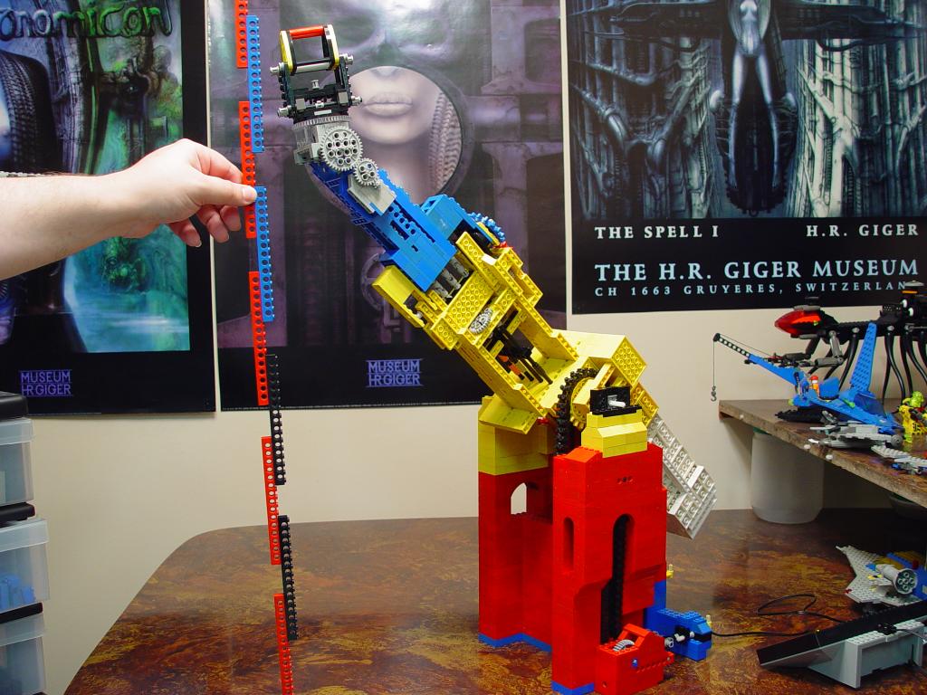
Maximum and minimum reach elevations.
The lowest the arm can reach is about 9 studs below the base, and the highest it can reach is about 84 studs above the base.


Reaching for a small ship... Grabinated!
The blue one-minifig craft above is about the limit of the arm's lifting ability because anything heavier will destroy the claw mechanism. I could have strengthened the construction to compensate but that would have reduced the clearance around the claw halves and would have made it heavier.
MLcad files
Note that neither of these model files contains step-by-step instructions. They're meant to be looked at in MLcad and pulled apart. Make sure you have all the latest parts packs installed in LDraw!

Wrist and gripper model
Here's an LDraw/MLcad file containing the complete structure of the wrist joint and gripper. There are two problems with the gripper as shown. One is that it's weak - forcing it open will pop off a brick that anchors the central worm gear in place. The second is that there is room for the worm gear to slide along its axle, which means that there is significant play in the mechanism. Even so, I'm very happy with this part of the model. I decided not to try to fix these problems because it would have made the gripper bulkier and heavier.

Power train model
Here's another model definition for LDraw or MLcad (I recommend MLcad for this one because it contains some non-Lego primitives). This one shows the complete power train of the arm - all the moving parts. The rest of the construction is left out for clarity and is left as an exercise for the reader.
There are a few things to note about the above model:
- Axle lengths are not exactly as they are in the real arm.
- LDraw lacks models for four types of gears I used in the arm. Specifically the 9-tooth (red), 15-tooth (blue) and 21-tooth (yellow) large-toothed gears from sets like 803, and a 36-tooth double-beveled gear from 10076. I've used the nearest equivalents I could find in the LDraw part set. The colored gears are easily spotted. The 36-tooth gear is represented in this file by the first 40-tooth gear along the path from the motor to the yellow shoulder gear (the large grey gear near the bottom left of the image at right).
- LDraw also lacks models for the type of chain/tread that fits on the large-toothed gears. This is the kind of chain used as caterpillar treads in sets like 780 . I've used red belts generated by MLcad to show where these chains are used in the arm model.
- I left out the transmission controls. They are represented here by the five blue axles. Pushing on them engages axles, as shown, and pulling on them disengages.