

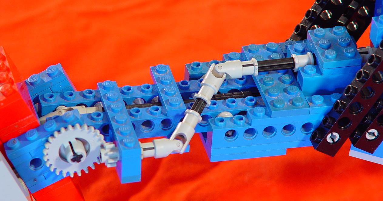
Views of the whole arm from both sides. Click to embiggen.
I started out working on a rotating chair at the end of a boom, for use in a large spacecraft cockpit or mad scientist's lab, but after I had made the first mockup I realized I had the basis of a robot arm. It kind of grew automatically from there. I already knew how to make simple multi-axis joints from having disassembled my Armatron toy robot arm, and I applied that knowlege here.
The arm as shown here is as far as I am going to take this design. I learned a lot from doing it, and I'm going to start over from scratch and attempt a much more functional arm.
This arm has four degrees of freedom:
- The end effector has one rotating shaft that can be used to swivel something, such as a drill or scoop, or open and close a claw. There are no motion limits on this axis other than those imposed by the chosen attachment. The above pictures show it with my first gripper design (not very good) attached.
- The wrist bends up and down and has a range of a little over 180 degrees.
- The elbow bends horizontally and has slightly less than 180 degrees of freedom.
- The shoulder rotates the arm up and down and has a very limited range of motion - about 75 degrees or maybe a bit less.
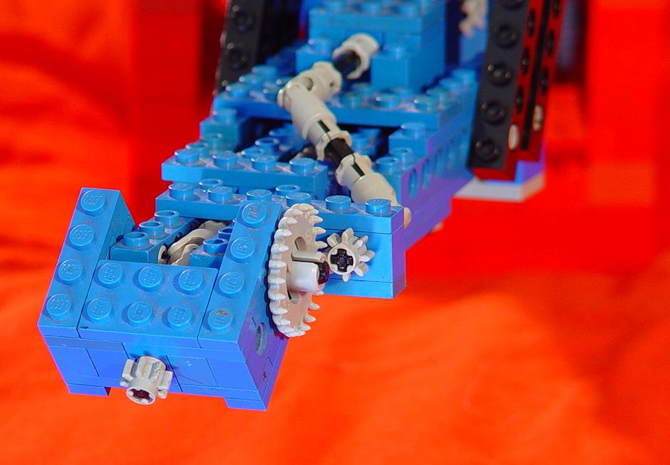
Wrist detail.
Here are a couple of close-ups of the wrist joint. I'm not too thrilled with the use of two universal joints to center the wrist axle, but it did work smoothly.

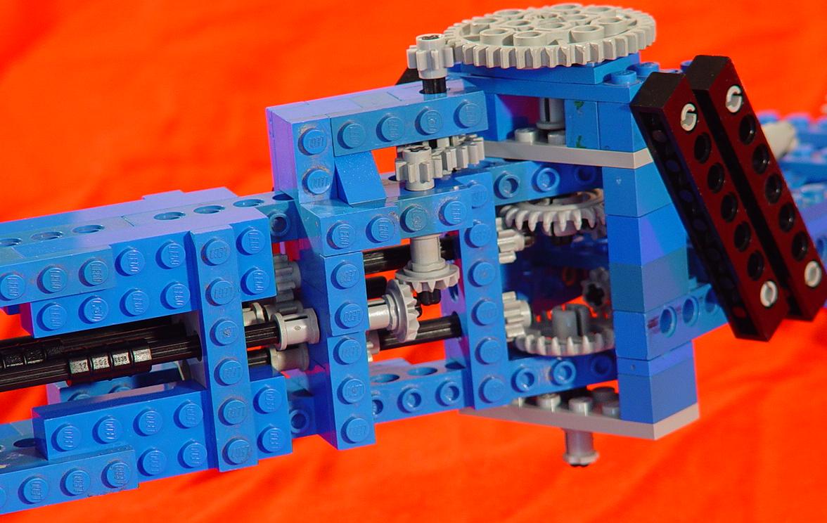
Elbow detail.
Closeups of the elbow joint from the left and right sides. The big gear on top moves the elbow. The two crown gears in the middle move independently of the joint and each other, and transmit the axle motions for the wrist and end effector through the elbow joint. At the elbow I use gears instead of universals to relocate the axles, but I'm still not happy with the complexity of it all.
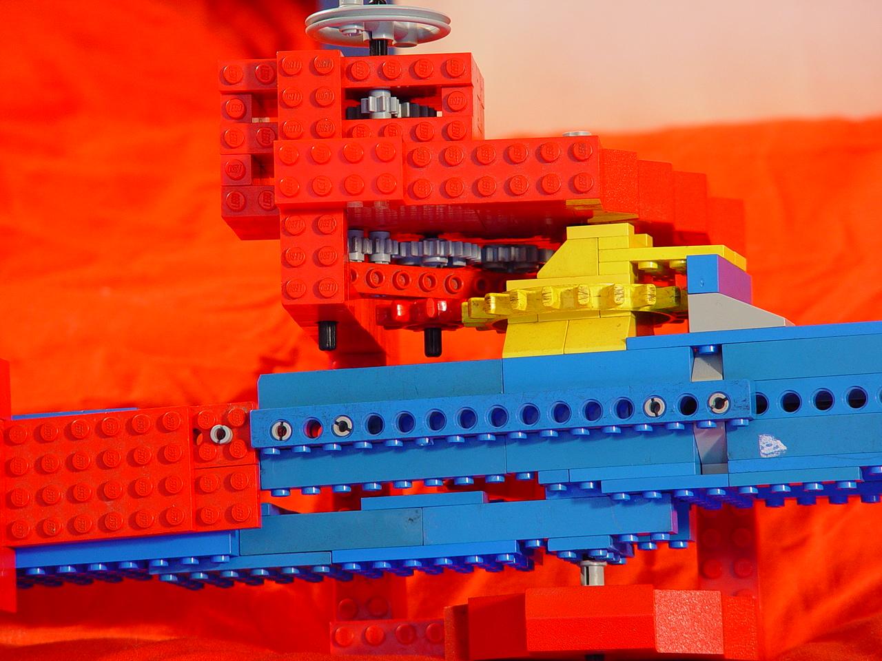
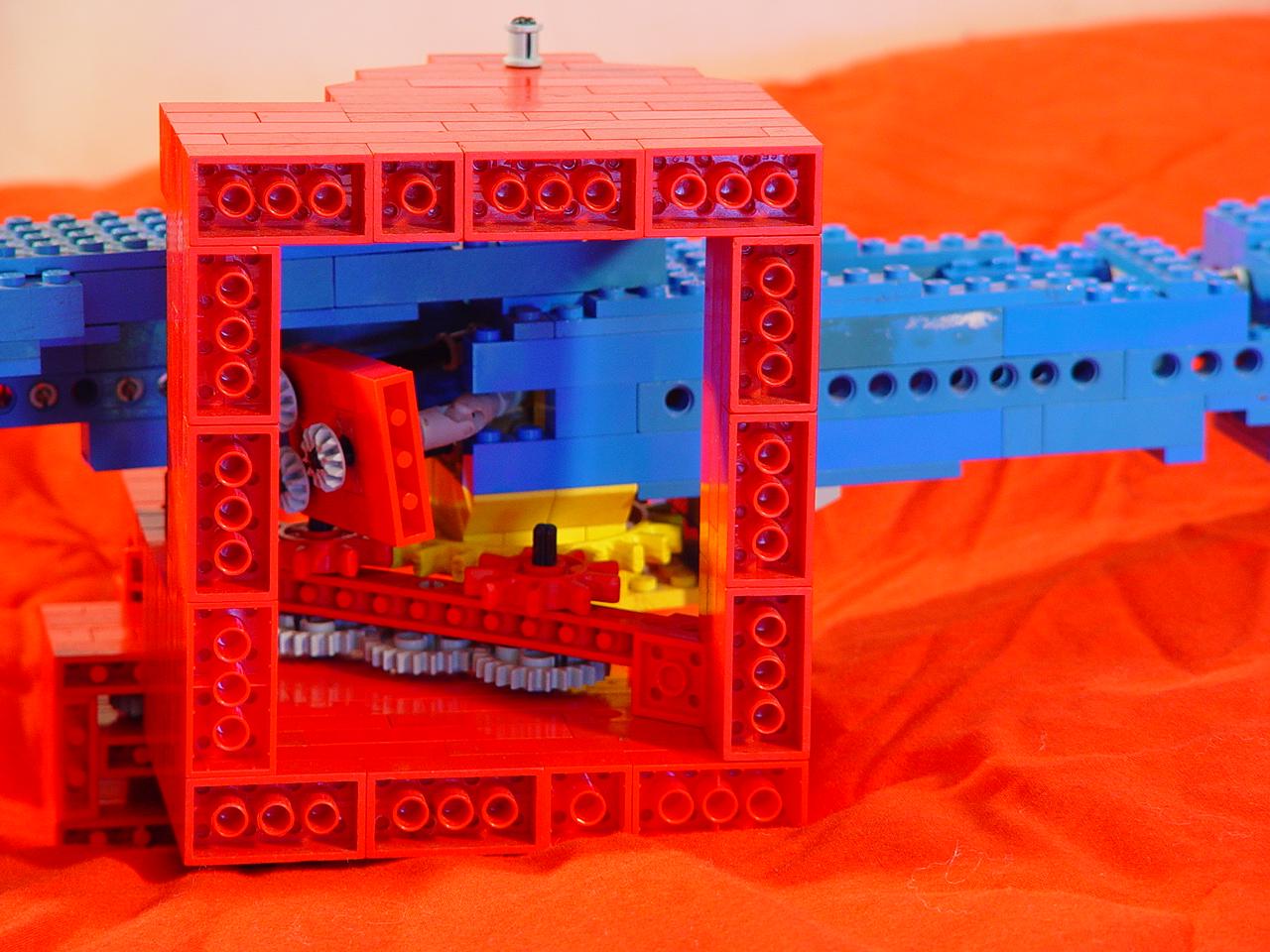
Shoulder detail from above.
Here's a top view of the shoulder. I'm using the biggest gear I have - the yellow old-style big-toothed kind - to move the arm, but it still needs a counterweight at the back end. I thought using two smaller gears to drive the larger one would provide more strength and finer control, but it doesn't work as well as I thought and ultimately all of the stress is still transferred to one small gear. I have ideas for a better multiple-interface gearing of the shoulder joint for my next design.
Shoulder detail from below showing unfinished transmission.
The underside of the shoulder joint. The three dangling crown gears in the middle are the ends of the drive shafts for the elbow, wrist and end effector. I was going to convert them to vertical shafts to the base of the arm here, but ran out of gears and decided to rethink my whole design.
My next robot arm design will have a much better gripper, which I have already designed. The wrist joint will have both tilt and rotation. I hope to simplify the elbow joint a bit, improve the gearing of the shoulder, finish running all the drive shafts to the base, and add a rotation axis for the entire arm. I have some ideas for powering the whole thing with a single motor, which would make it almost a Lego clone of the Armatron. I'm waiting for some new gears to arrive before I tackle the new arm design.
The type of axle-joint pass-through I use for the wrist and elbow has the obvious drawback that moving one axis can cause unintended motion of the subsequent axes. This is a problem the Armatron shares, and at this time I don't know how to avoid it.