Linear Timelapse Robot v1
(Project completed: 2015-07)
This is a long and technical read. If you just want to see the finished product, check out the video in the Results and Conclusions section near the bottom.
Motivation
A few years ago, a fellow photographer and I were discussing qualities of good timelapse movies, and the observation was made that camera movement adds a lot of impact.
Since the filming of a few seconds of timelapse video can easily occupy hours of real time, a mechanism is needed to assist in moving the camera smoothly during the recording. The mechanism should preferably be able to provide precise positioning and operate automatically.
There are existing products on the market that do this, called timelapse rails, but professional models typically run $600 and up into the thousands. I wanted to see if I could make a DIY model super cheap using mostly material commonly found in hardware stores, and easily obtained electronics.
In the remainder of this article I'll cover the design of the electronics, the physical construction, and then the results.
Requirements
My requirements for this prototype were:
- Motion range of at least three feet; must be able to produce noticable motion relative to foreground objects on the order of several feet away.
- Positioning accuracy to within a millimeter; because this isn't for close-up work, small inaccuracies are unlikely to be visible in the final video.
- Battery powered for outdoor shooting.
- Simple ease-in/ease-out motion plan but with tunable parameters.
- Should only use off-the-shelf hardware, and electronics that are easily sourced.
- Support for heavy cameras; point-and-shoot weight only.
- Fast motion, as that would require heavier motor and battery.
Electronics
I've split up the schematic into multiple sheets for readability; this works well for this project since it has multiple independent subsystems.
I chose to use the Teensy++ 2.0 microcontroller development board as the heart of this circuit since I already had one on hand and it's very easy to program. It is grossly overpowered for the needs of this project, but I prefer to go for ease of development in the prototyping stage and then find a best-fit chip once the final version is designed.
LCD Interface

LCD and Camera Interface schematic. Click for full size.
I chose to use an Optrex DMC-20261 20-character by 2-line LCD display module for visual display because I had a bunch of them lying around in my scrap heap that I had picked up at Active Surplus years ago. This module uses the Hitachi HD44780 LCD controller, which is extremely common. Any LCD module using this controller chip can be substituted here for the Optrex model I used, though different units have varying numbers of displayable characters.
Once you have the software written to control the LCD module, the interfacing is easy; you just need four bidirectional data lines, three control lines and a potentiometer to tune the LCD's contrast. My Teensy pin assignments for the control lines are port C bits 0-3 for the data lines, bit 4 for Register Select (command/data mode on the LCD), bit 5 for the read/write signal and bit 6 for the Enable (latching) signal. Port C is shared with the camera control interface, described below.
The LCD interface was the first part of the circuit I made work, because it was useful to have a textual output path for debugging.
Camera Control
For reasons I may describe elsewhere, some other time, I normally make my timelapse movies out of sequences of individual photos rather than by removing frames from video or using a specialized video camera.
Thanks to the magic of CHDK it is really easy to make a circuit that triggers the camera at regular intervals - you just need something that briefly applies a 5V pulse to one pin on the camera's USB connector, and you need to enable remote triggering in the CHDK menu. Even without CHDK this is doable if your camera supports an external trigger switch - just take the switch apart and wire it up to whatever form of electronic control is appropriate.
Since only one bit is needed to fire the camera, and I had a spare bit left on port C, I used port C bit 7 as the camera control output as shown in the above schematic. What the schematic doesn't reflect is that it's actually wired to an RJ45 jack which makes it easier to securely connect a coiled stretch cable to the moving camera dolly, and on the dolly another RJ45 jack is connected to the USB plug that goes into the camera. The RJ45 cable has some unused wires that could potentially convey power and communications to electronics on the dolly in future designs.
Keypad Interface
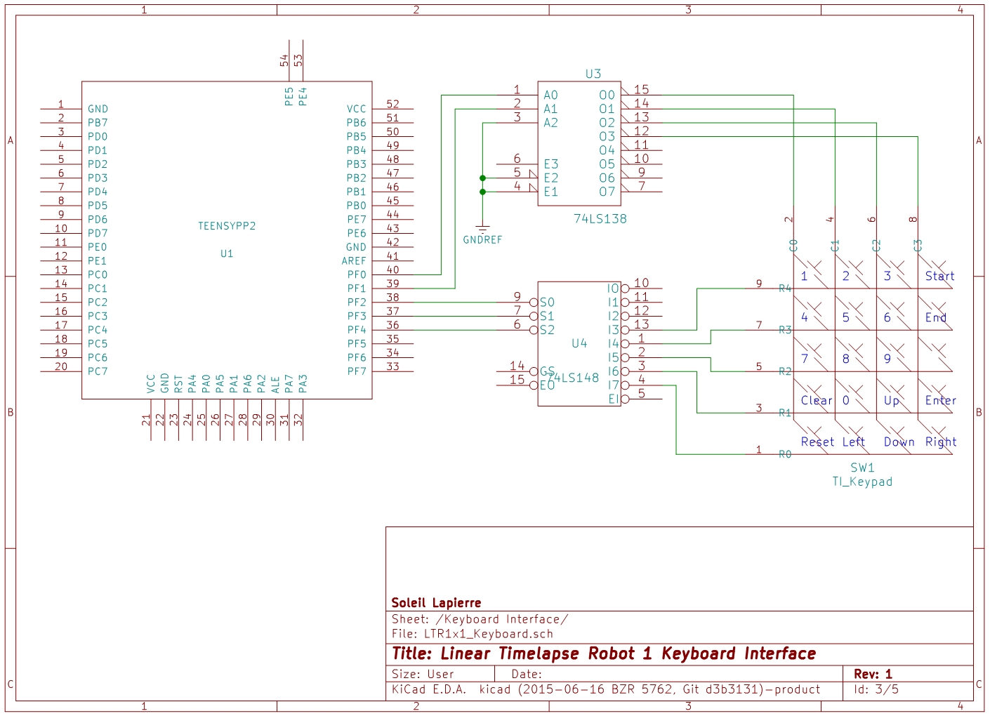
Keypad Interface schematic. Click for full size.
Another useful bit of scrap I had lying around was a simple, unlabeled chiclet keypad made by Texas Instruments. I haven't been able to find any data about them online, but they're easy enough to figure out with a multimeter; just a matrix of row and column wires bridged by the button switches.
While the Teensy has enough ports available that I could have used an I/O line for each row and column of the keypad, I was trying to keep I/O usage down in aid of using a smaller, cheaper microcontroller in future. Also I did not need to support any simultaneous keypresses for this project, so I used a 74LS138 binary decoder to drive the four column lines from two output bits (port F bits 0 and 1) and a 74LS148 binary encoder to convert the five column lines into three input bits, port F bits 2 through 4. Yes, I know I'm wasting capability on these two chips but there really aren't any more economical selections among standard TTL, and this way there is room to expand the keypad in future.
An interrupt service routine running on the Teensy periodically increments the two-bit value output to the decoder to scan the next column, and checks for an input value from the encoder to see if a key is pressed.
I'm relying on timing to debounce the keyboard buttons. Keyboard columns are polled at 250Hz, which with four columns means each key is effectively checked every 16mS. That isn't quite slow enough to prevent all double keypresses from happening, but it seems to catch most of them. If it were irritating me enough I would debounce further by either making sure each key had the same state on two successive scans before counting it as a press or release, or reducing the polling frequency.
By the way, ports C and F were chosen for physical convenience - they're both near the bottom end of the Teensy module, on opposite sides.
Motor Driver
Before starting this project I spent some time shopping around for a suitable motor to use. I ended up using this motor I found in the surplus bins at Princess Auto. I think it might be a car power window motor, but I'm not sure. Anyway, it's a 12V DC motor with an internal worm gear and the output is via a rotating square hole that is open on both sides, so you can poke a square axle all the way through. It has a good tradeoff between power consumption, torque and speed.
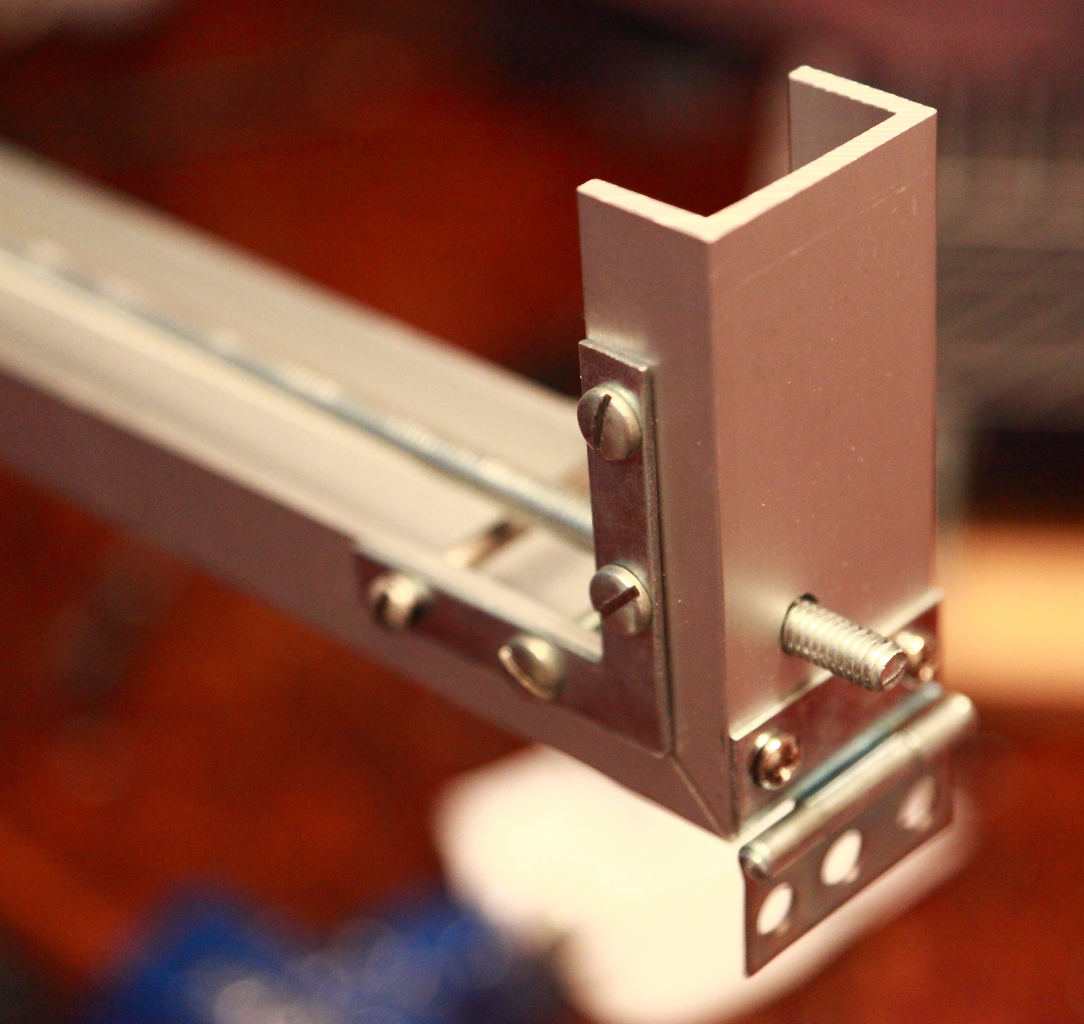
I should mention that I had also put some thought into how I was going to move the camera dolly up and down the rail. I eventually decided to try using a 1/4" threaded rod as the drive shaft after seeing a demonstration of some of Zaber's motion control products at the Vancouver Mini Maker Faire. I ground one end of the rod down to a square profile that would fit through the axle hole in the motor I had chosen, and used a make-shift Kotter pin both to prevent it from sliding out and to hold a break-beam encoder disc in place on the end. The picture below shows this assembly.
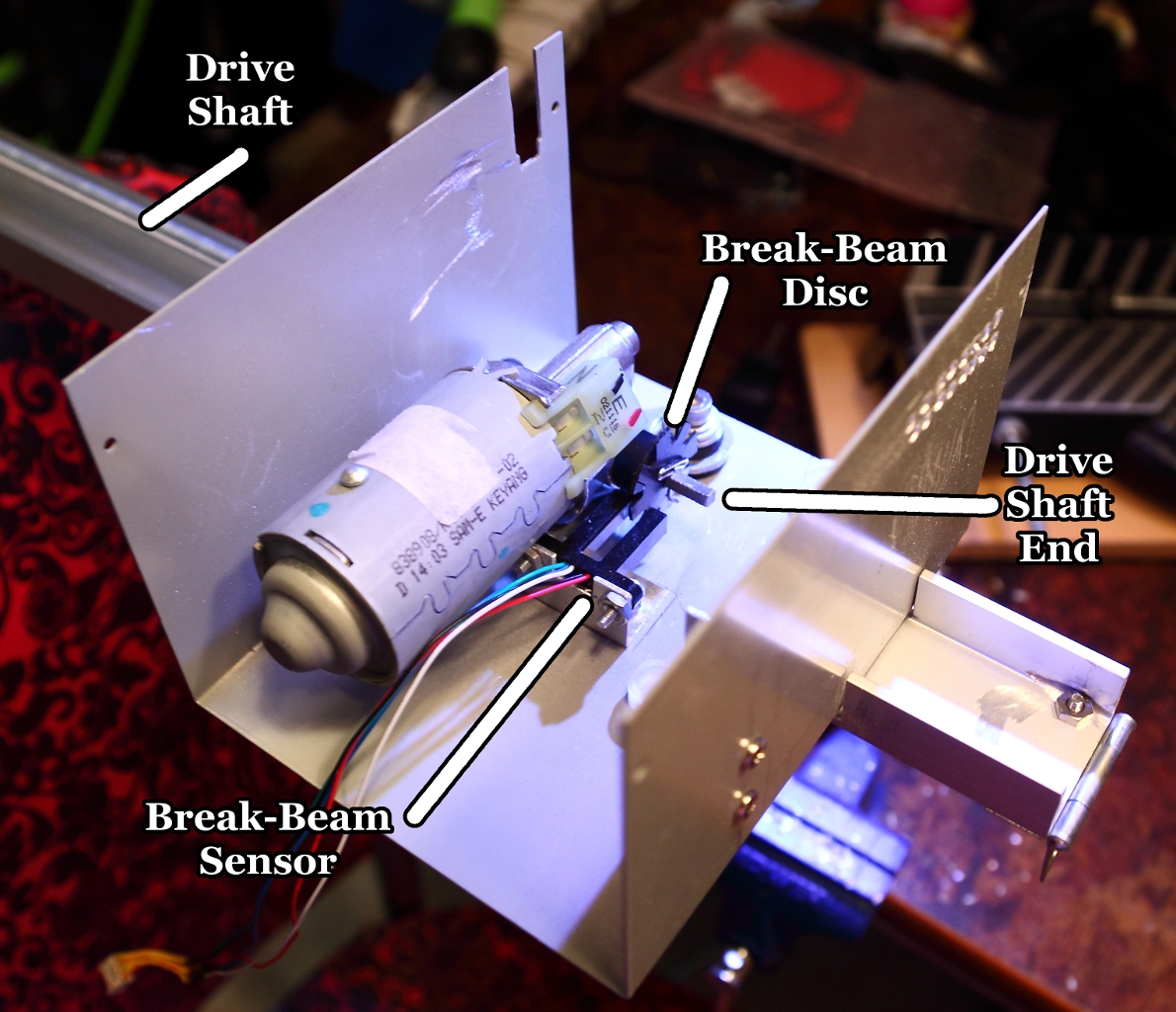
Motor Assembly. Click for full size.
Zaber uses stepper motors to drive the shaft, but steppers are more expensive and more complex to control than normal DC motors, so instead I planned to use a break-beam sensor to measure the motor's rotation in order to determine when to stop it. Since my prototype doesn't have super high precision requirements and has fairly high friction between the drive shaft and load, overshoot isn't a problem.
I started out designing my own H-bridge motor driver using power Darlington transistors, but then a friend pointed out that single-chip solutions exist. I switched to using the L298N driver because it's readily available at both of my local electronics suppliers and breakout boards and prototyping kits are also available. This solution worked very well for me.
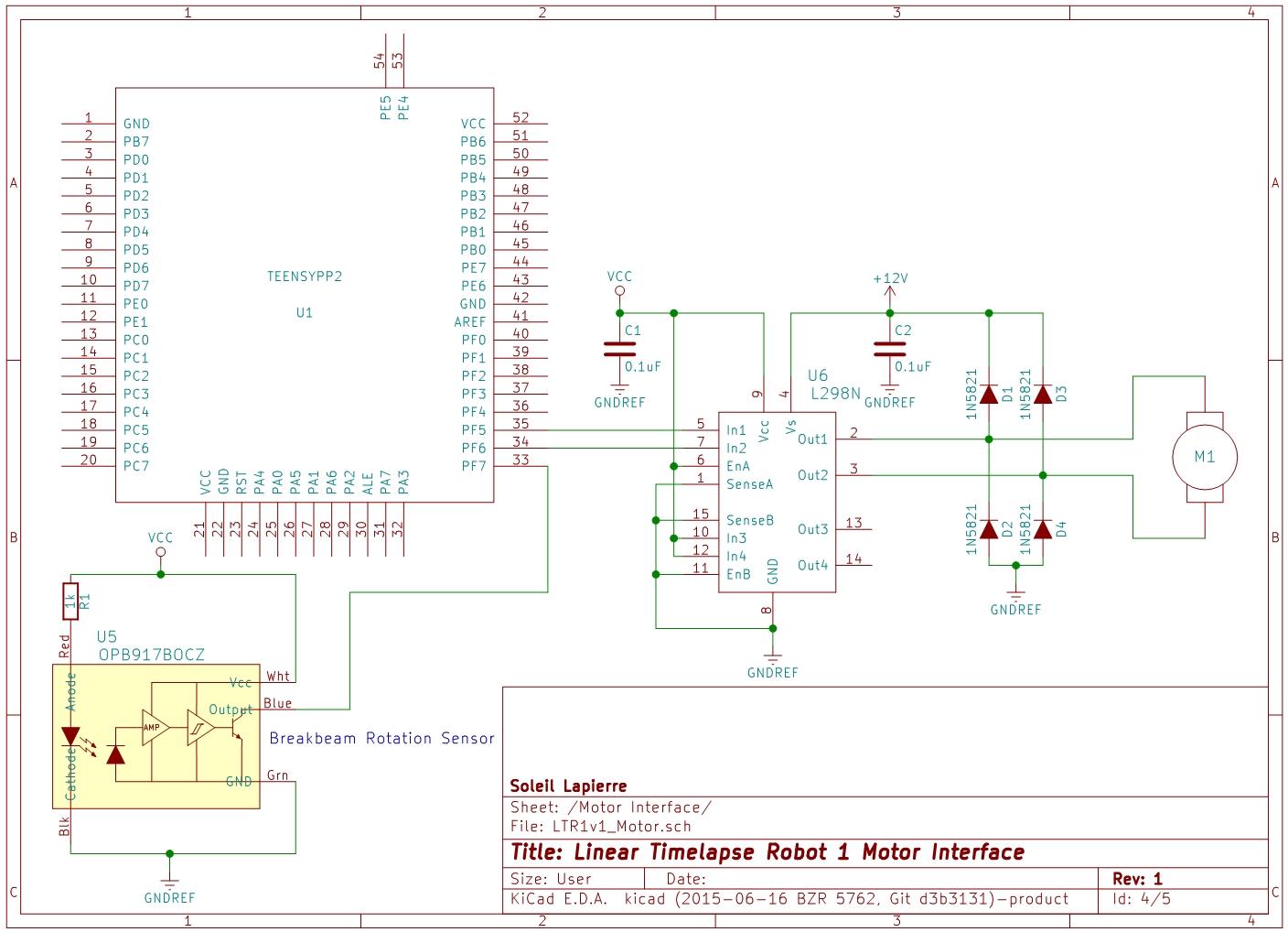
Motor Interface schematic. Click for full size.
The above schematic shows on the right side the L298N wired up to the motor. The four diodes are to prevent back-EMF generated by the motor when it stops from damaging the circuit. I'm actually only using half the L298N here - it's capable of controlling two DC motors or one stepper motor, and I could have wired the two halves in parallel to double its current capabilities when driving a single motor, but that was not necessary. It was easier to use it this way than to try to source a single-bridge device.
Each bridge of the L298N has three control inputs - two that control the motor direction if their levels are different, or force a stop if they're the same, and one enable signal that can be pulsed to control the motor speed. Since I always want maximum speed I just tied the enable line high and connected the other two inputs to port F bits 5 and 6 to control the direction. I had originally wired enable to port F and used a single bit to control the motor direction via an external inverter chip, but I ended up not needing the inverter for anything else so switched to this control scheme to eliminate a chip from the circuit.
For measuring the motor's rotation I affixed a plastic disc with eight notches cut in the edge to the drive shaft, and used a break-beam optical sensor to detect the passing of the notches. This lets me measure 1/16ths of a rotation by detecting both rising and falling edges in the sensor output. Given that the drive shaft I used is 20 thread count, meaning 20 spiral windings per inch, this measurement scheme gives me a resolution of 320 sensor counts per inch of linear movement, or a movement resolution of approximately 0.08mm ignoring play and overshoot.
The optical break-beam sensor I'm using is an OPB917BOCZ which was chosen for its physical dimensions (easier to find a fit with my motor mount) and for its TTL compatibility. I actually made a component selection error here and chose a device with an open-collector output by accident, requiring the addition of a pullup resistor to make it logic-level compatible. I should have chosen the non-OC version. The Teensy does have software-selectable internal pullup resistors in its inputs, but they proved insufficient and I had to add an additional 10K pullup resistor to the circuit (not shown).
The optical sensor output is routed to port F bit 7, and this line is polled by the same interrupt service routine that polls the keypad. More about this ISR in the software section below. So all told the circuit uses 16 I/O pins on the Teensy. Sharing ports between multiple functions proved straightforward once I learned how to avoid interference between the different software modules.
Power Supply
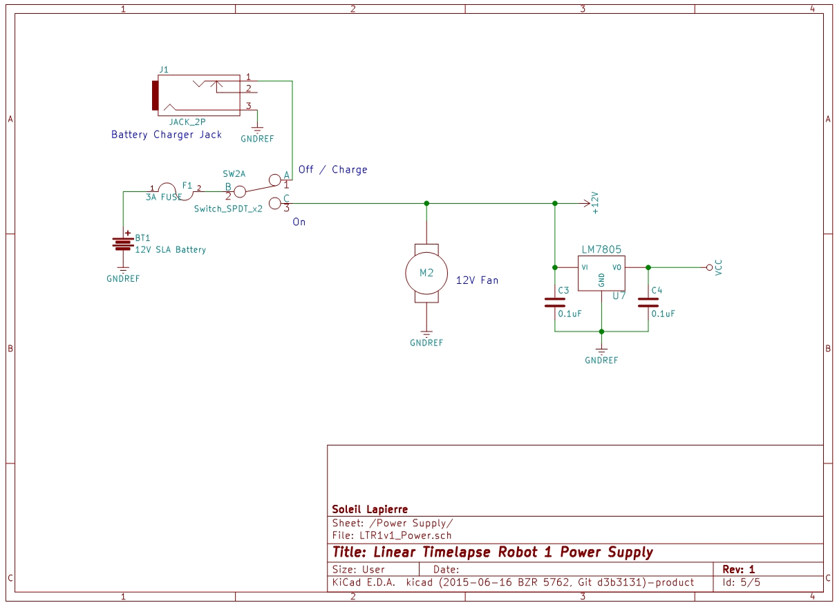
Power Supply schematic. Click for full size.
The power source is a 12V 1.3Ah SLA (Sealed Lead-Acid) battery. This battery may be slightly underpowered for the needs of the motor; it can supply enough current but the lifetime of the battery may be reduced by the high draw (the motor draws about two amps when running). This was the cheapest high-current rechargeable battery that would fit in the enclosure I had already chosen, and SLA batteries are safer than the expensive LiPo batteries used in drones.
A fuse protects against short circuits. A switch turns the robot on, or in the off position connects the battery to a jack for the battery charger; since the case has to be disassembled to get the battery out, I thought it prudent to enable in-place charging. Another switch built into the charger jack ensures the connection is not live when the power switch in the off position unless the charger is actually connected.
A 12V DC fan cools the motor driver circuit, and an LM7805 voltage regulator supplies logic-level power to the microcontroller and other 5V parts of the circuit.
Software
The C source code for this project is here if you're interested in looking at it. It's divided up into modules for each I/O subsystem plus some shared code such as the simple state machine I used for both the menu system and the timelapse filming loop. You'd need the Teensy++ 2.0 development tools if you wanted to compile this.
This project uses the code I previously developed to drive the Hitachi LCD controller chip. Most of the rest of it should be fairly self-explanatory, I hope. The only noteworthy parts are heavy use of state machines in the menu and motion control systems, the timer ISR which I will discuss below, and sharing of I/O ports between the different subsystems which is accomplished by being careful to only change the states of port bits relevant to the active code.
Timer
There is a single timer interrupt service routine (in timer.c) that fires 1,000 times per second. To accomplish this I used the Teensy's 8-bit timer with a count of 250, and the SysClk/64 tap for its clock signal. With the main system clock set to 16MHz, this gives 16,000,000 / (250 * 64) = 1,000 Hz. I wanted this rate as the basis for real time measurement, so I could specify motion control timing parameters in seconds or milliseconds easily in the user interface.
The timer ISR also polls the keypad and motor sensor inputs, via a callback. The callback only does the actual input polling every 4th call (ie, 250Hz) as that is sufficient to accurately measure the motor rotation and more than enough for the keypad polling. I could have set up separate timers for these additional functions or used interrupts driven by input pin state changes, but then the chip would have been spending more time in interrupt context switching overhead and I would have been using more hardware features without need. I went with a single ISR and used only one timer in order to maintain better compatibility with possibly less capable microcontroller selections in future designs.
I do realize that use of this timer ISR affects the accuracy of cycle-counting delay routines, which I also use in this project, but I do not need them to be super-accurate; all my accurate timings are based on the ISR tick count.
Motion Control
The menu system offers the user the ability to enter parameters for the initial velocity of the camera dolly, its acceleration/deceleration rate, its maximum velocity, the camera trigger pulse width, the exposure time to allow before moving the camera, and the desired total interval between camera frames. There are also some menus for testing various subsystems.
Once the user starts the motion control program, operation is automatic until either the Reset or the End button is pressed. End means to enter the deceleration phase and slow the camera movement to zero, then end the session. Reset is the panic button, and halts all operation immediately.
The motion control loop is expressed in a state machine so may be non-obvious from looking at the code, but the idea is simple. The steps in the loop, ignoring user input, are:
- Trigger the camera.
- Wait until the exposure duration has elapsed.
- Add acceleration to velocity and compute the next move distance.
- Start the motor, measure drive shaft rotations until the right distance is reached, then stop the motor.
- Wait until the desired inter-frame time interval has passed relative to step 1, then go to step 1.
Construction
Mechanical
I'm not going to provide plans or great detail about the physical construction because although I'm proud of how this, my first metal construction project, turned out, I have to admit it is a poor design and not deserving of emulation in any way.
Rail end detail. Click for full size.
The backbone of the rail is made from an 8' length of 1.5" aluminum channel. I cut off a few inches at one end and reattached it angled upward at 90° to support the far end of the drive shaft and provide a stopper for the dolly, as shown above. At the opposite end I cut a notch out of the sides within which to nest the clamshell enclosure containing the motor and electronics. Everything is fastened together with nuts and bolts because I do not have welding equipment yet, nor a safe place to work with high temperatures.
I attached small hinges to each end of the rail. By using 1/4" wing nuts these hinges can be securely attached to the heads of tripods, enabling an easy way to incline the rail and stand it on uneven terrain. You'll see this arrangement in the test run video in the results section below.
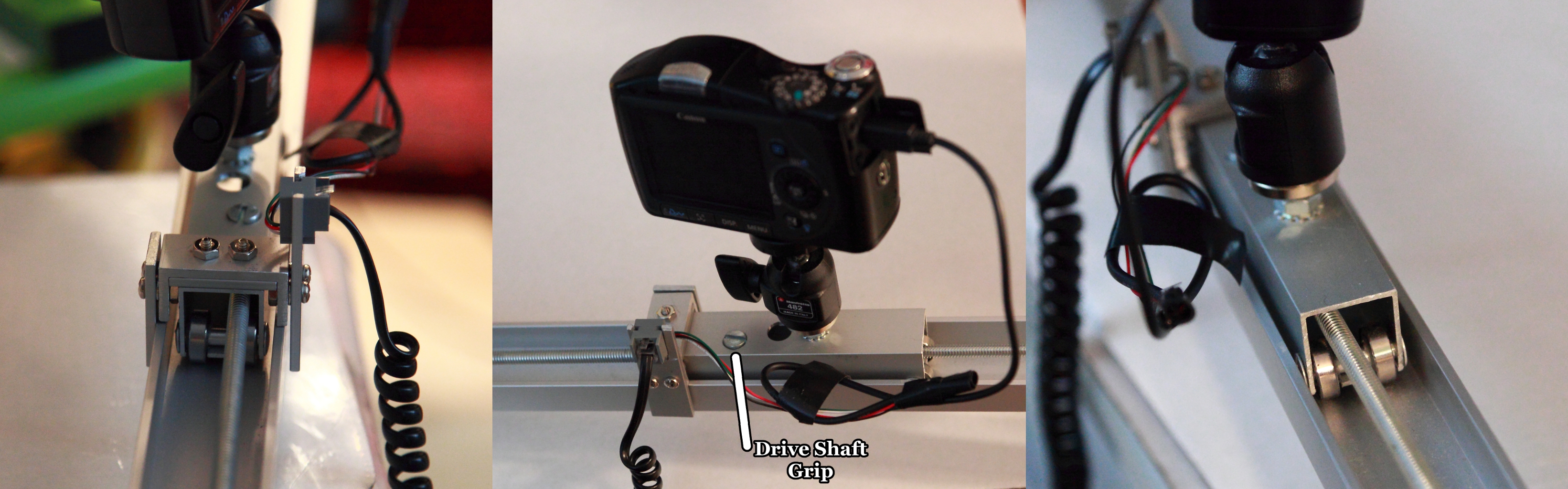
Dolly detail. Click for full size.
The most complex part of the mechanical system is the moving dolly. Lacking a 3D printer or access to a milling machine, I made it from a short section of square aluminum tubing. Four wheels made of small bearings on axles made from Chicago screws support the weight of the camera. The camera itself is mounted on a 1/4" carriage bolt projecting from the top. The attachment to the threaded drive shaft is accomplished with a cross dowel nut , the top of which you can see projecting near the camera mount, as indicated in the middle image above. I drilled a small hole in the other end of the nut by which it is anchored to the dolly from the bottom with a small screw. This method of attachment was the best I could improvise with standard hardware store components, and has one advantage in that it has a degree of rotational freedom which relieves some of the strain resulting from flexing of the drive shaft.
In my initial tests the dolly was too unstable, easily tipping over in response to the torque of the drive shaft. I added stabilizing fins that ride just above and beside the edges of the rail, and that helps significantly. Although the dolly still does bounce around quite a bit while moving, it always settles back into an upright position.
The drive shaft is a 6', 1/4" threaded rod acting as a worm gear to move the dolly. In practice a 1/4" drive shaft at this length proves to be far too flexible; it droops under its own weight and thrashes around under torque, producing vibration and often irritating rattling sounds when it bounces off the rail floor. A 5/16" shaft might work better, but would also be significantly heavier and would require a stronger and heavier motor to turn. Also a stainless steel shaft might not thrash as much but I was unable to find one long enough.
Electrical
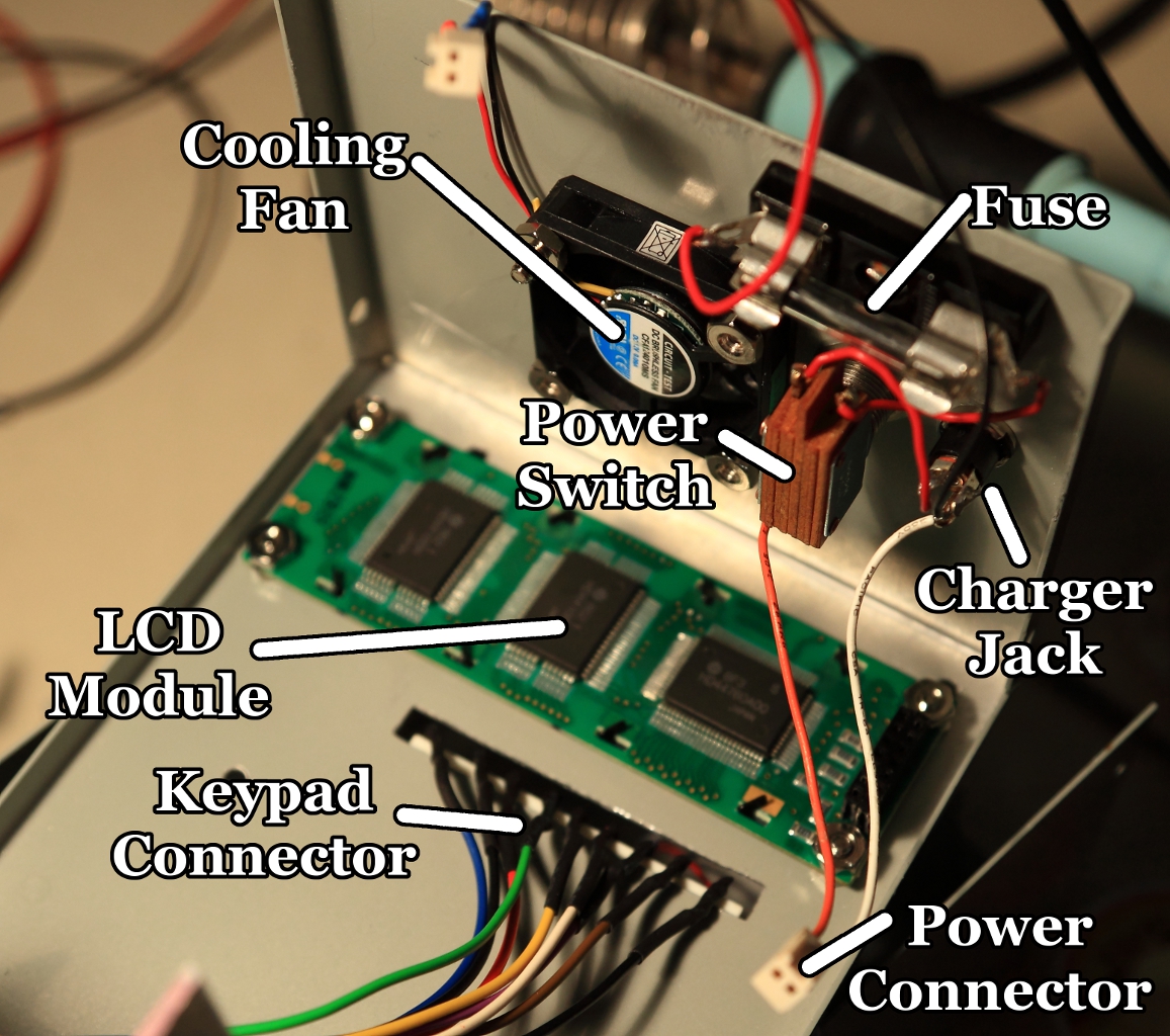
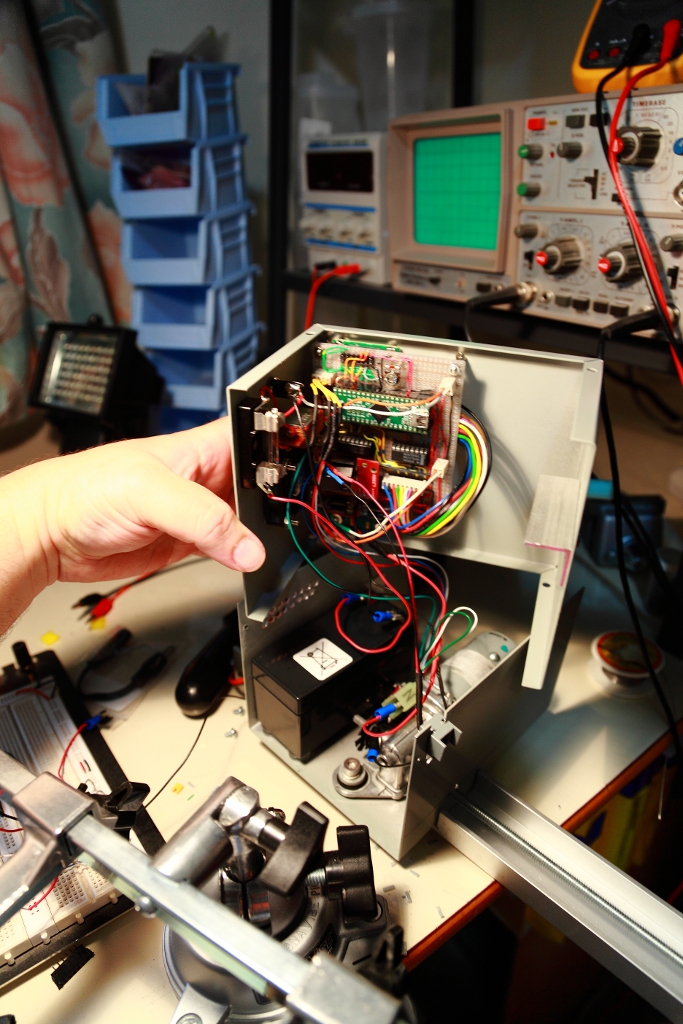
External controls mounted. Click for full size.
The above image shows the external controls mounted inside the hop half of the clamshell enclosure. The keypad is attached to the top side (out of view here) with double-sided tape. The fan and switches are on what will be the rear of the case when it's closed. A previous image in an above section already showed the motor mounted in the lower half of the clamshell. Two L-shaped aluminum brackets form the restraints for the battery when the shell is closed.
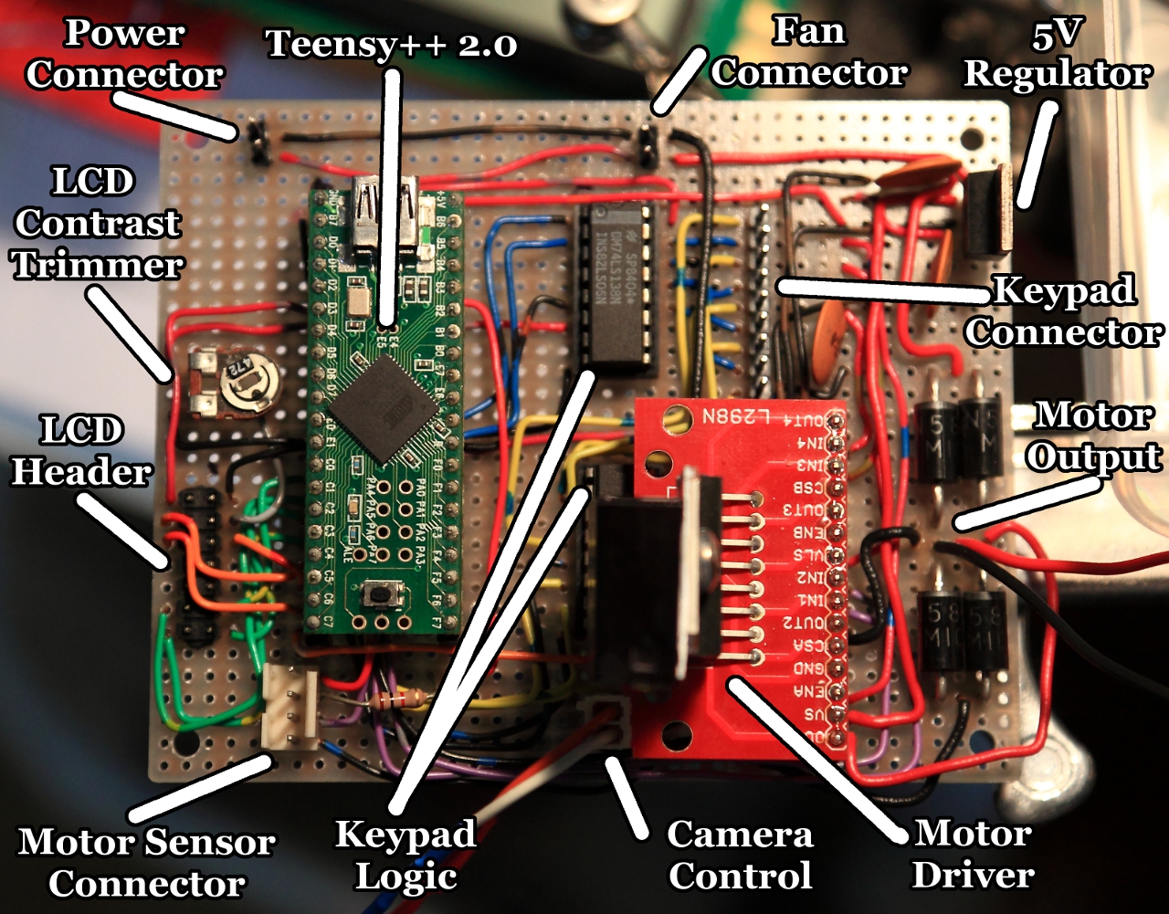
Populated protoboard. Click for full size.
The photo above shows the protoboard with all components mounted. The other side just has the solder connections. As with a previous microcontroller project I did for an online course, I used protoboard that has pairs of adjacent holes joined on the back side, and I'm finding I hate that type. It's too hard to cleanly solder connections that involve more than two wires, such as power distribution strips. From now on I'm going to try to stick to protoboard that has groupings of 5 or 6 and preferably predefined power strips.
I had some trouble mounting the Teensy on the protoboard. I didn't want to solder it on because it needs to be removed to update its firmware and because I want to be able to steal it for other projects. But the header pins it comes with are too fat to insert into a normal DIP socket, and using a ZIF socket would have made the soldering job much harder because ZIF sockets are fat and would cover adjacent holes in the protoboard. So I improvised a socket out of female headers, including only the pins that actually needed electrical connections so as to keep the friction down, and that worked very well.
All parts mounted. Click for full size.
The above photo shows all the components installed, including the battery, and all connectors in place. The case is ready to be closed. And finally the picture below shows the finished and closed case. I printed out a sticker to overlay on the keypad, and the QR code just points to this web page.
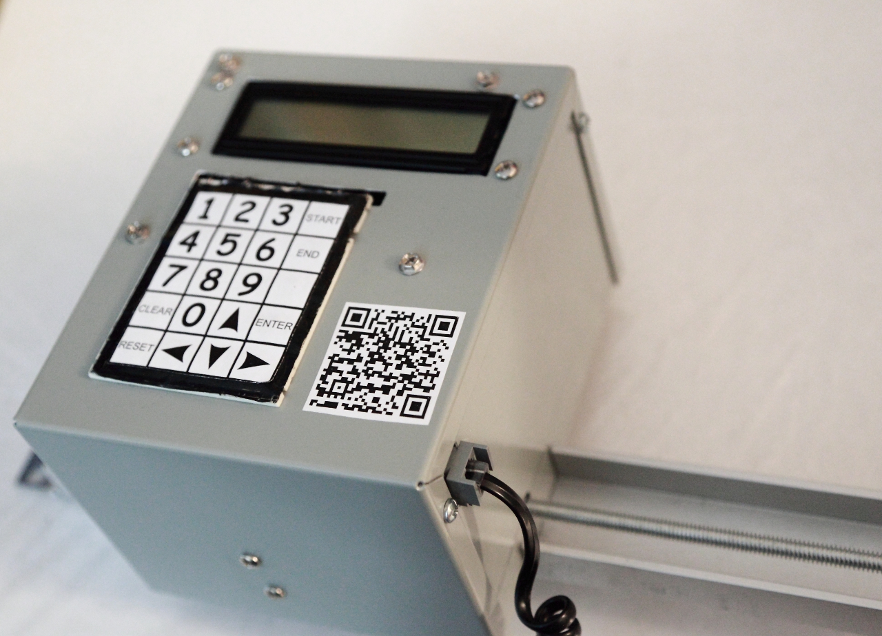
Case closed! Click for full size.
Results and Conclusions
Here's a short video giving a quick tour of the menus, some footage of the robot in action, and example timelapse results before and after post-processing. Note the loss of focus in the first half of the test footage is due to a bug in the camera I used, which I forgot to work around. The weird lighting and haze are because this was shot during a week when the city was blanketed in smoke from forest fires.
I would estimate the overall cost of this project's building materials at between $200 and $300, not counting tools and time. That makes it less of a value proposition than I had hoped relative to professional camera motion systems.
When I first conceived this project there were very few DIY timelapse rail projects online. Now there are many, and some of them better than mine, but that's a good thing. More open hardware designs means more power in the hands of the budget enthusiast, and this was still an excellent learning experience for me. It was my first metal construction project, my first serious robotics project, my second microcontroller project, and very satisfying to see in finished form. "I made this!" is a great feeling.
Overall I call this a successful prototyping project because it works, looks good (to my eye anyway), accomplished what it was supposed to and I learned a lot from it. I have some good improvement ideas for the next version, but for now there are other projects I want to work on so I will be setting this aside for some time.
Learnings
Things I learned during this project:
- 1/4" threaded rods are too flexible to make good drive shafts at lengths over about 2'.
- Having quality tools helps immensely. I have a good variable-angle miter saw for which I had to order from England to get a hacksaw blade, but I did not regret it at all. A metal- biting tool, drill press, good set of drill bits, assortement of files, table clamp and Dremel kit were also indispensable. And a vacuum cleaner for picking up all the metal shavings.
- Debugging microcontroller code can be hard if it doesn't have in-circuit debugging. I solved about half the bugs on this project by careful inspection of the code rather than by trying to get data back from the running program.
- I need to pay more attention to component placement on circuit boards. My protoboard nearly didn't fit in its assigned position in the case because some components were too close to the fan and power switch.
- Life is too short to have to be making deliberate solder bridges under cramped conditions because of protoboard that sucks.
- Working with metal is easier and more fun than I expected. I really do want to learn to bend and weld metal now though.
- What works in your mind may not work perfectly on the breadboard. What works on the breadboard may not work perfectly once fixed in solder.
- I love heat-shrink tubing! This is the first project I've used it on, and it's a wonderfully clean-looking way to protect wire joins. There is no going back to electrical tape after this!
Future Improvements
Here are some thoughts I've had about possible future improvements to this project.
- Instead of the floppy and noisy 1/4" threaded rod drive shaft or the heavier 5/16" one, I'm going to look into using a chain or steel cable to move the dolly.
- I may use a heavy-duty stepper motor instead of a DC motor. That'll give me an excuse to learn more about stepper motors anyway.
- The next version should be capable of supporting a full DSLR camera with a reasonably heavy lens. This means a stronger motor and more capacious battery, which means a heavier aparatus overall. That's fine, and I plan to build small wheels into one end so it can be dragged to location instead of carried.
- It would be nice to also have the ability to rotate the camera as part of the motion control program. I have been considering making a second motion control robot that does pan and tilt, and I will try to make it so the two can be combined and their programs chained to produce aggregate motion.
- It would be nice to be able to script camera parameter changes along with the motion, like zoom and focus distance. How practical this is depends a lot on the particular camera, and will require some research.
- It must be possible to author arbitrary motion curves using splines rather than this version's simple acceleration / max speed model. The motion programs should be authored on a PC or tablet and transferred to the robot via USB, memory card or Bluetooth.
- It would be nice to have live control over the robot from a tablet via Bluetooth, or via USB from a PC.
- The next version must have better dolly stability and faster settling time, and be quieter!
- It should also have faster motion, or optionally smooth enough motion that the dolly can move continuously while the camera shoots, without blurring the shots.
- The dolly must have limit switches on its ends, both for safety (to avoid crushing fingers) and to enable the motion control software to detect the ends of the rails and thereby do absolute positioning.
KiCad files
This is the first project for which I've done the schematics using KiCad. I normally use gEDA but it was unavailable when I needed it because of some trouble with my Linux box. Anyway, I couldn't find KiCad symbols for some of the components I used in this project so I made my own. Help yourself:
- Basic Symbols - currently just a DC motor symbol.
- Breakbeam - Symbol for the OPB917BOCZ breakbeam sensor.
- L298 - Symbol for the L298N dual H-bridge motor driver.
- LCD - Symbol for the Optrex DMC20261 LCD module.